In the final segment of our four-part series for electric utility grounding, we will address some of the unique challenges and hurdles faced when temporary protective grounding (TPG) is used with systems energized at 600 volts or less.
OSHA Provides Some Guidance
OSHA Directive CPL 2-1.38, “Enforcement of the Electric Power Generation, Transmission and Distribution Standard”, dated June 18, 2003, provides some guidance for grounding systems energized at 600 volts or less. Line 11 of Appendix B: Clarification of Major Issues, on page B-12 states in part as follows (all emphases added):
“Paragraph (n)(4)(i) requires protective grounding to be capable of conducting the maximum fault current that could flow at the point of grounding for the time necessary to clear the fault. The maximum fault current on electric power distribution lines operating at 600 volts or less is typically high enough to melt the phase conductors carrying the fault current. Available fault currents on 600-volts systems may be in the range of 13,000 to 80,000 amperes.”
The OSHA directive also admits, “If protective grounding equipment were required to carry the maximum amount of fault current without regard to whether the phase conductors would fail, the size of the grounding equipment would be impractical.”
And it further states, “However, the standard does not require the protective grounding equipment to be capable of carrying more current than necessary to allow the phase conductors to fail. Thus, a protective grounding jumper sized slightly larger than a phase conductor would be sufficient to meet paragraph (n)(4)(i).”
Obviously, a TPG jumper “sized slightly larger than the phase conductor” can itself be quite impractical based on the actual size of the phase conductors, be it an uninsulated power line or rigid bus section. This also doesn’t take into consideration the grade or size of the clamps needed to connect the jumper(s) to the line or bus. The largest commercially available clamp is Grade 7 or 7H for the fabrication of TPG assemblies according to ASTM F855-09 – ‘Standard Specifications for Temporary Protective Grounds to Be Used on De-Energized Electric Power Lines and Equipment’ and may be problematic for employers to meet, not to mention especially difficult for the employee to use.
ASTM F855 Table 1 (X/R ≤ 1.8), describes Grade 7 as a copper cable size of 350 kcmil or two 4/0 (Grade 5) used in parallel, while Table 2 for systems with high X/R ratios (X/R = 30), is Grade 7H, which is limited to only 350 MCM (please note MCM is the same as kcmil).
Just for reference, the outside diameter of a 350 MCM cable is over 13/16 inches! Considering the average weight of bare copper 350 MCM cable is a little over one pound per foot (without clamps or ferrules), using the entire TPG assembly quickly becomes a power lifting competition.
“However, if the impedance of the grounding equipment does not contribute to delay in the operation of the circuit protection devices and if the impedance of this equipment is low enough to provide a safe work zone for employees [as required by paragraph (n)(3)] (the establishment of an EPZ), the employer will be in compliance with paragraph (n)(4)(ii).”
We must remember overall impedance (Z) in an AC circuit is dependent upon a combination of both resistance (R) and reactance (X), specifically inductive reactance (XL). Resistance is relatively easy to identify and can result from loose connections and/or dirty or surface corrosion.
But inductive reactance can be caused by the physical positioning of the cables and several other factors. Simple oversights, such as neatly storing excessive lengths of the TPG cable in coils (forming an inductor), wrapping the ground cable around a ferrous pole or object, or leaving unused cable in the metal storage reel mounted to the bucket truck’s frame, can significantly increase inductive reactance.
Such small and seemingly insignificant actions can substantially increase the overall impedance of the temporary grounding assembly. This can, in turn, not only delay the operation of overcurrent protective devices, but can also cause the entire assembly to fail catastrophically.
When using TPGs with systems energized at 600 volts or less, if the engineering analysis determines a particular size of ground cable(s) is necessary, either used as single conductors or in parallel, to adequately carry the fault current, all the following three conditions must be satisfied by the employer:
Be able to handle the available fault current
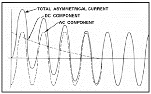
Account for the total asymmetrical current stresses from the DC offset combined with the AC component (see Figure 1).
Have an overall impedance that will not delay the operation of protection devices.
Figure 1
Two Standards That Must Be Considered When Paralleling TPGs
Lastly, if the grounding jumpers necessitate paralleling, then they must be derated, and there exist two commonly used standards to determine the derating multiplier.
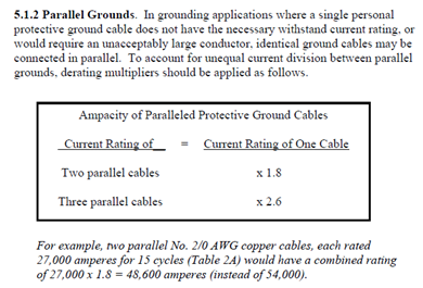
The first one is the US Bureau of Reclamation Facilities Instructions, Standards and Techniques – Personal Protective Grounding for Electric Power Facilities and Power Lines,* dated 2005, and it states: “In grounding applications where a single personal protective ground cable does not have the necessary withstand current rating, or would require an unacceptably large conductor, identical ground cables may be connected in parallel. To account for unequal current division between parallel grounds, derating multipliers should be applied as follows…” (see Figure 2).
Figure 2
The current rating of two parallel cables should be derated by a factor of 1.8 of a single cable and a factor of 2.6 for three paralleled cables. Additionally, paralleling more than three grounding cables is not recommended by the USBR.
“…the added electromechanical forces (EMF) due to the use of multiple TPGs are most likely a greater factor in derating the ampacity of the multiple TPGs than are the unequal current division between TPGs. While some references suggest at least 10% derating due to thermal considerations, the EMF require a much higher derating factor. In recent testing by NEETRAC, the derating due to EMF can be 30% to 50% or higher.”
Summary
Unfortunately, many electric utility employees, including electricians, linemen, engineers, and safety professionals, consider the use of temporary protective grounding as a relatively basic skill, requiring only a rudimentary concept that employs very little thought process or advanced planning.
However, as we’ve seen through this series of articles, nothing can be further from the truth. Correctly sizing and installing TPGs requires thoughtful actions, skills, knowledge, and experience, which are absolutely critical for full employee protection from any source of re-energization once the lines or equipment has been deenergized and placed under the protection of a LOTO or clearance order.
TPGs are like the insurance policy on your high dollar vehicle. It’s not pleasant to pay the monthly premiums or take time out of your busy schedule for regular maintenance, and it is a little frustrating obeying the traffic laws when everyone else on the road seems to disregard them. However, if the unthinkable should ever happen, you’ll be very glad you proactively fulfilled your responsibilities.
Thus, to ensure your TPGs are sufficient, adequate for the job, and placed correctly requires proper training for the end-user, the engineers who determine sizing and installation locations, and all other affected stakeholders. We at e-Hazard have a team of highly qualified and experienced electrical engineers and trainers who can help you accomplish these important goals to ensure your workers are adequately equipped for temporary protective grounding at any voltage level.
* USBR Facilities Instructions, Standards and Techniques Volume 5-1 – Personal Protective Grounding for Electric Power Facilities and Power Lines, Dated July 2005, Section 5.1.2, page 12 of 81.
** IEEE 1246-2020 – Guide for Temporary Protective Grounding Used in Substations, Section 4.8.3, page 26.
George Cole joined the e-Hazard team in 2021 as an electrical safety instructor and consultant specializing in the electric utility industry. He has worked for the largest electric utility company in Arizona for over three decades, holding various technical roles in several departments (building electrical maintenance, T & D, radio telecommunications, electric power generation, etc.). George is currently assigned to the Palo Verde Nuclear Generating Station as their electrical safety consultant and is the “Subject Matter Expert” (SME) in all matters related to electrical safety. George holds credentials as a Certified Electrical Safety Compliance Professional (CESCP) and a Certified Electrical Safety Worker (CESW) from the NFPA and serves as a member of NFPA’s Certification Advisory Group (CAG) for the CESCP and CESW. He is also a member of the Electrical Safety Industry Working Group (IWG) within the nuclear power industry, where he is considered an electrical safety expert among his peers.
Hello, and thank you for the article. I am involved in specifying protective grounds for 2700 kVA transformer, 34.5/0.69 kV. The maximum symmetrical short circuit value is 42 kA on the 690 volt side, with an X/R of 11.7. The challenge is that for a fault on the secondary of the transformer, the only protective device is the high side expulsion fuse, which will take approximately 1.7 seconds (yes, 102 cycles) to clear the fault. I’m having difficulty figuring how to specify the grounding cables, ball studs, or any of the equipment. Looking at the IEEE 1246, the tables go no higher than a symmetrical value of 30 kA for a 180 cycle clearing time, and using a 60 cycle clear would not be conservative enough.
Drew, thanks for your question. This is a unique situation, and not covered with the intent of ASTM F855. Personal grounding for safety is intended for “reasonable” trip durations, and cable testing is conducted likewise. The concept is a “momentary” fault, not such incredibly long durations.
Honestly, these types of setups require engineering solutions to lower trip times if at all possible. Issues with faults of incredibly long durations introduce many other factors, like copper loss, huge magnetic forces, cable derating due to time after the first few cycles. As the fault continues, heat builds, copper’s resistance increases with the heat, and the cables become less and less effective.
Feel free to contact our engineering department for assistance with this issue. We will be glad to assist. Use this site and scroll to the bottom to click on “Contact Us.”