Those of us who have been in the electrical trade for some time will likely remember using analog meters with needle pointers, such as the trusty Simpson 260 VOM (Volt, Ohms, Milliamperes). These robust, accurate, and reliable test instruments were the standard for countless electricians and technicians for a good number of years. And while they are still available and used today, their popularity has diminished, and their scope has been limited to special applications as they have been replaced with the simpler design of digital multimeters (DMM).
Digital Multimeters
DMMs have been around for several decades and, like their analog predecessor, have proven themselves time and again to be an invaluable tool for electrical workers during troubleshooting and testing. They have countless helpful secondary functions, such as checking for continuity, resistance readings, determining the health of capacitors, etc.
One important feature of a DMM is to accurately test for presence of voltage. Even more importantly, they can test for the absence of voltage, to assure us that the part(s) we are about to touch is completely deenergized when establishing an Electrically Safe Work Condition (ESWC).
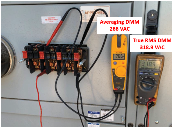
While there are many manufacturers of high quality DMMs, they can be generally categorized into two basic types: True Root-Means-Square, abbreviated as “RMS,” and Averaging RMS, also called Average-Responding meters. The two types are sometimes misunderstood or confused as the same, but significant differences exist, especially how they can affect electrical safety.
While this is not an electrical engineering article, we should cover some of the basic high-level mathematical equations, which will aid our understanding, as we will delve into the basics of Root-Means-Square (RMS) voltage and Average voltage. From there, in Part 2, we will move to the two types of DMMs commonly available and their limitations. Finally, we will explore the reasons why all electrical workers should be selecting one over the other.
What is RMS?
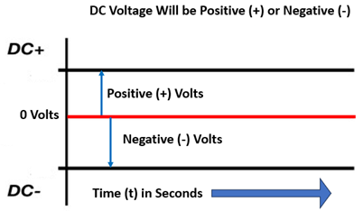
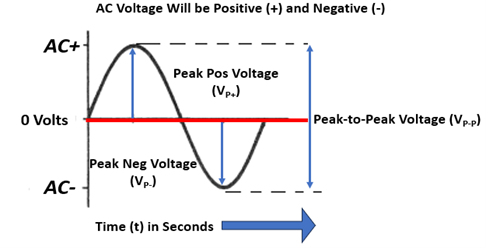
RMS, which is also called “effective value” and identified as VRMS, is the AC voltage that will produce the same amount of heat or power in a resistive load as provided by an equivalent DC voltage. Unlike DC, which has a relatively constant positive (+) and negative (-) voltage for a given period of time, as shown in Figure 1, alternating current oscillates through changes in both polarities within a period of time, as shown in Figure 2.
AC voltage rises and falls, from zero volts to a maximum positive (+) voltage, then back to zero. But it continues to swing into the opposite polarity to its maximum negative (-) value and falls once again to zero volts, in a sinusoidal waveform, better known as a “sine wave.”
Additionally, you may recall other terms such as “Peak Voltage” (VP), which is the maximum voltage of one polarity, or “Peak to Peak” (VP-P) voltage, which is the potential difference across both polarities and are key components of sine waves.
Figure 1 - Steady DC Voltage in Relation to a Time Period
Figure 2 - Sinusoidal AC Waveform Varies in Relation to a Time Period
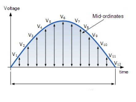
Because an AC voltage and AC current change polarity in relationship to time, their instantaneous values at any given point in time vary as the voltage rises, peaks, then drops back to zero. So they are not constant, as seen in Figure 3 of a positive half cycle.
The increments in Figure 3, also called “mid-ordinates,” identified as V1 through V12, will all have a different voltage, with V6 being the peak voltage of the positive half cycle (VP+). The same occurs in the negative half cycle. Consequently, the changing waveform inherent to AC circuits is unable to produce the equivalent heat or power as a DC circuit of the same voltage.
This dilemma forced electrical engineers and mathematicians to develop complex equations to bridge the difference between AC and DC to establish an equivalency for power and other capabilities.
Figure 3 - Positive Half of a Sinusoidal Wave Divided into 12 Mid-ordinates
The rate at which the voltage or current changes from positive to negative per one second of time is the frequency and is measured in ‘cycles-per-second’ (CPS) or, more commonly, in Hertz (Hz). In the U.S. and North America, the standard frequency is 60 Hz; however, a lower 50 Hz is common in other parts of the world, such as Europe, Asia, Africa, and South America.
The RMS voltage (VRMS) can be calculated by the following equations from either the peak voltage (VP) or peak-to-peak voltage (VP-P):
VRMS = 1 / √2 x VPor 0.7071 x VP
VRMS = 1 / 2√2 x VP-Por 0.3536 x VP-P
However, as mentioned earlier, confusion can exist with some, who mistakenly believe that the RMS voltage (VRMS) is the same as the average voltage (VAVG), or “mean value.” While the two are very close in value and are certainly related, they are not identical, as shown by the following equations:
VAVG = 2VP / π or 0.637VP
VRMS = π / 2√2 x VAVGor 1.11 x VAVG
As the name implies, the average voltage (VAVG) is derived from the sum of all the mid-ordinates in one full sine wave divided by the total number of mid-ordinates in the same sine wave. The greater the number of mid-ordinates sampled, the greater the accuracy of the average voltage (VAVG).
But regardless of how accurate an average voltage (VAVG) is calculated to, it is not the same as the RMS voltage (VRMS) unless it is multiplied by a factor of 1.11.
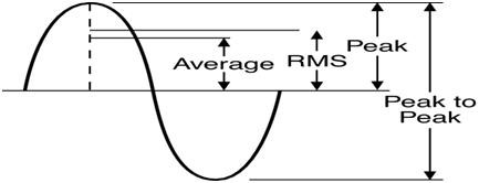
In conclusion, the VRMS will always be equal to or greater than the VAVG but less than the VP or VP-P, as seen in Figure 4. These are not interchangeable properties.
Figure 4 - Comparison of VAVG, VRMS, VP and VP-P
Now that we understand AC as it relates to DC, and the basic differences between Average, RMS, Peak, and Peak-To-Peak voltages, we will transition to the topic of multi-meters in Part 2.
George Cole joined the e-Hazard team in 2021 as an electrical safety instructor and consultant specializing in the electric utility industry. He has worked for the largest electric utility company in Arizona for over three decades, holding various technical roles in several departments (building electrical maintenance, T & D, radio telecommunications, electric power generation, etc.). George is currently assigned to the Palo Verde Nuclear Generating Station as their electrical safety consultant and is the “Subject Matter Expert” (SME) in all matters related to electrical safety. George holds credentials as a Certified Electrical Safety Compliance Professional (CESCP) and a Certified Electrical Safety Worker (CESW) from the NFPA and serves as a member of NFPA’s Certification Advisory Group (CAG) for the CESCP and CESW. He is also a member of the Electrical Safety Industry Working Group (IWG) within the nuclear power industry, where he is considered an electrical safety expert among his peers.
Some of the new EVs generate a modulated DC signal from the main EV battery, through an inverter to AC, and then back to DC. This signal MUST have a true RMS meter to read that created DC wave, which is more of a ripple wave form from the rectifier.
Using the wrong meter will indicate zero volts DC, which presents a serious life safety issue, especially with EV batteries approaching the 1000 Volts DC level!
The article states “In conclusion, the Vrms will always be equal to or greater than the Vavg…”
When would Vrms ever equal Vavg?
The only answer I can think of is if Vavg equals 0 which is not a helpful use case. Would it be better to state that Vrms is always 11% greater than Vavg?
Some of the new EVs generate a modulated DC signal from the main EV battery, through an inverter to AC, and then back to DC. This signal MUST have a true RMS meter to read that created DC wave, which is more of a ripple wave form from the rectifier.
Using the wrong meter will indicate zero volts DC, which presents a serious life safety issue, especially with EV batteries approaching the 1000 Volts DC level!
Wow Ken that’s a real eye opener and another reason why we should always choose true RMS multimeters in our workplaces.
The article states “In conclusion, the Vrms will always be equal to or greater than the Vavg…”
When would Vrms ever equal Vavg?
The only answer I can think of is if Vavg equals 0 which is not a helpful use case. Would it be better to state that Vrms is always 11% greater than Vavg?