Within the electric utility industry, once employers and employees have completed section (m) requirements in 1910.269 for properly deenergizing the electrical supply of transmission and distribution (T&D) equipment, the next required activities are found in section (n) Grounding for the protection of employees.
“When This Section Requires Protective Grounding…”
This section addresses specific requirements of temporary protective grounding (TPG), covering transmission and distribution lines, as well as generation and “other equipment.” A note containing two caveats appears just before the general requirements to ground in 1910.269(n)(2), adding a little more confusion to the TPG discussion:
Note to paragraph (n)(1): This paragraph covers grounding of generation, transmission, and distribution lines and equipment when this section requires protective grounding and whenever the employer chooses to ground such lines and equipment for the protection of employees. (Emphasis added)
The first caveat, “when this section requires protective grounding,” is relatively self-explanatory and points back to transmission and distribution lines and equipment as dictated in section 1910.269(n)(2). But like all “clear” OSHA regulations, there are additional exemptions to grounding that must be taken into consideration. These exemptions will be discussed later in the article.
“Whenever the Employer Chooses to Ground…”
The second caveat, “whenever the employer chooses to ground,” is more than a bit vague. At a high level, the user could interpret this to mean, “I don’t necessarily HAVE to install TPGs per OSHA requirements, but IF I choose to, THEN I MUST follow ALL of section (n) that apply to my TPGs.”
For example, a generation plant has a 13.8 kW generator that is going to be lockout or tagout in accordance with section 1910.269(d) to support downstream maintenance activities. However, the employer may choose to ground the indoor metal-clad switchgear fed by the station’s auxiliary transformer for other electrical maintenance work.
This choice to ground may be because the employer chooses to do so and/or the manufacturer’s instructions of the switchgear instructs the equipment to be grounded. This grounding may be accomplished via insertion of grounding devices commonly called “ground trucks/buggies/carts” or alternative switchgear grounding methods (e.g., applying properly-sized personal safety grounds on built-in grounding ball and socket joints).
The Typical Generation Plant’s Power Circuit
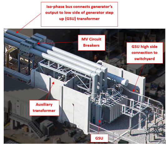
To assist readers who are not familiar with a typical generation’s plant’s power circuit, here is a brief description from the generator’s output to the power grid (see Figure 2 below). Be aware that not all utility generating plants use the same circuity design and/or layout.
Figure 2 - Typical power plant generator to switchyard circuit
As noted in Figure 2, the generator output (out of view inside the building) connects directly to rigid segregated bus segments commonly called “isophase bus.” The isophase buses may or may not be equipped with a medium-voltage (MV) isolation device (e.g., an air circuit breaker, vacuum circuit breaker, gas-insulated switch or gas-insulated breaker installed in the bus). This isolation device usually will be located in the circuit before the low side of the generator step-up (GSU) transformer. The iso-phase bus can also connect to the station’s auxiliary transformers to provide power to in-house loads (again, not in all designs).
The generator’s output voltage normally falls within the parameters of “medium voltage equipment” according to ANSI C84.1, Voltage Rating for Electric Power Systems and Equipment (60Hz), with electric potentials in the range as low as 690 volts AC up to 24k volts AC. However, the high side of the GSU is often stepped up to high voltage (HV) or extra high voltage (EHV) as defined by ANSI C84.1, in the range of hundreds of thousands of volts commonly used with electric transmission systems. The GSU’s high side windings use specialized bushings connected with bare overhead lines to provide current to the switchyard, which in turn feed the transmission grid.
Grounding in an Outage
In the case of a (hypothetical) planned outage, one of the activities being performed during a generator outage is maintenance on equipment downstream from the generator’s output, such as metal-clad MV fused isolation switches/breakers, enclosed bus duct, or switchgear. The tasks include lubrication, torque checks, cleaning, inspection and insulation testing, often called “meggering” in the field. (Note that Meggar is a brand name). In this case, workers will be physically touching exposed parts that are energized during normal operations.
The affected equipment is deenergized under the LOTO requirements of 1910.269(d). Then a choice is made to ground the generator’s output line-side of the switch/breaker as well as its output on the load-side. By making this choice, which technically may not be required by OSHA, the employer is now required to install TPGs in accordance with all the applications and limitations of 1910.269(n). However, isolating and deenergizing the overhead lines from the transmission grid, which is connected to the high side of the GSUs, is normally done inside the switchyard, traditionally falling under the responsibility of the T&D system operator under 1910.269(m).
And, as previously addressed in Part 1, proper coordination between the generation plant and the T&D system operator is crucial. In such cases, grounding the overhead T&D lines is mandatory per 1910.269(n)(2) rather than optional.
A similar mandate would apply to grounding of a 13.8kV compressor or pump motor whenever using LOTO. In other words, IF the choice is made to ground, THEN all of section (n) must be followed, including correct grounding cable sizing, installation/removal sequence, etc.
Transmission & Distribution Grounding
Transmission and distribution sectors do not allow OPTIONAL grounding because 1910.269(n)(2) REQUIRES T&D to be grounded according to very prescriptive and necessary instructions found in 1910.269(n)(3) through (n)(8). These sections are as follows:
Section (n)(3) – Equipotential Zone
Section (n)(4) – Protective Grounding Equipment
Section (n)(5) – Testing for Voltage
Section (n)(6) – Connecting and Removing Grounds
Section (n)(7) – Additional Precautions
Section (n)(8) – Removal of Grounds for Test
As stated above, while all these sections must be followed for T&D, they must also be adhered to IF the employer chooses to ground, like in generation plants or with other MV utilization equipment.
Exceptions to Grounding in T&D
While section 1910.269(n)(2) is the requirement for T&D, there are allowed exceptions when grounds may NOT be required even within the T&D environment. This exemption to grounding is permitted if a utility finds itself in a condition where grounding is simply impracticable, or grounding would present greater hazards to employees. If so, then employees are allowed to work without grounds installed, but ONLY IF ALL THREE of the following conditions are met:
The lines or equipment are deenergized per section (m)
There is no possibility to contact other energized sources
Induced voltage hazards are not present
If the employer can demonstrate and verify with 100% certainty that all three conditions not only exist, but will continue to exist during work activities, then the lines or equipment may be treated as deenergized by isolation alone through a clearance order per paragraph (m), without applying TPGs.
However, and it must be strongly emphasized, the employer and employees must never take these three conditions lightly, especially in situations of possible induction or impressed voltages. Workers’ lives are literally at stake.
Working without temporary protective grounds and without an intentionally-constructed equalized potential work zone can lead to life-altering injuries and worker fatalities. And while induction may not exist at a point in time because adjacent lines or equipment not associated with the work scope are also deenergized, this “safe condition” can change without notice.
These lines, for example, can become energized from a variety of sources, such as a large motor auto-starting inside a power plant, causing induction to adjacent circuit(s); or an overhead line being re-energized from a different clearance, etc.
You get the picture – in an electrical utility, THINGS CHANGE!
To Be Continued
In Part 3, the authors will cover the hazards of induced voltages and its criteria in greater detail, as well as grounding at less than 600 volts within OSHA requirements.
Stay tuned! As always, your comments, thoughts, and feedback are most welcome and very helpful.
George Cole joined the e-Hazard team in 2021 as an electrical safety instructor and consultant specializing in the electric utility industry. He has worked for the largest electric utility company in Arizona for over three decades, holding various technical roles in several departments (building electrical maintenance, T & D, radio telecommunications, electric power generation, etc.). George is currently assigned to the Palo Verde Nuclear Generating Station as their electrical safety consultant and is the “Subject Matter Expert” (SME) in all matters related to electrical safety. George holds credentials as a Certified Electrical Safety Compliance Professional (CESCP) and a Certified Electrical Safety Worker (CESW) from the NFPA and serves as a member of NFPA’s Certification Advisory Group (CAG) for the CESCP and CESW. He is also a member of the Electrical Safety Industry Working Group (IWG) within the nuclear power industry, where he is considered an electrical safety expert among his peers.