TPG Review
We discussed in our four-part series on TPGs (Let’s Get Clear on Electrical Utility TPG – see below for links) the importance of properly applying TPGs in such a manner as to ensure electrical worker safety.
In these articles, we stressed the important applications that covered possible sources of induction, ensuring protective ground cable sizes, and much more.
Understanding Grounding
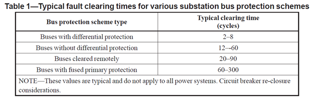
- Upstream Protection: Determining proper grounding cable and clamp ampacities depends on the upstream protective element, be it a set of medium-voltage fuses or an upstream circuit breaker, as well as protective relay schemes. IEEE 1246-2020 gives the following guidance when depending on relays, fuses, and/or breakers to determine maximum allowed fault current to the point of personal safety ground application:

Note here that, almost always, a remotely cleared bus will take longer to clear than a local relay, and, as shown, fused primaries are not the best solution.
In deciding what size TPGs to use, one can use ASTM F855 Table 1 if the X/R ratio is under 30, or ASTM F855 Table 2 for high X/R ratios (over 30). Using the withstand rating, the TPG cable and clamp sizes are determined by applying the upstream fault current and trip values to this table.
For typical commercial industrial users, this data is typically acquired from a site arc flash study through commercial software such as ETAP®, EasyPower® or SKM®. Utilities may use GIS-type software capable of determining exact short circuit currents and system impedances. Running a fault on the bus in the proper location will yield upstream fault current values, upstream trip time(s), and will provide the X/R ratio associated with that particular faulted condition.
These values will vary, of course, based on the individual scenarios (utility source versus backup generator source versus parallel utility and generator sources, etc.). All these faulted conditions and scenarios will yield specific values that apply only with those exact parameters and fault conditions.
The TPGs must be decided based on the exact situation that applies when the planned evolution is being carried out.
It is critical that the end-user understands the differences in IEEE 1246-2020 Table 1 above, based on the method of upstream protection.
It is just as critical (or more so if you choose) that the individual building the model for the arc flash software enter the exact conditions installed in the field and not blindly trust engineered drawings. Fuse types, breaker settings, relay settings – all of these factors can greatly affect the real-world conditions for the end-user who literally will be trusting these values for that user’s life safety.
2. Backfeed Potentials: We have looked at the supply-side fault currents and trip times, but what about potential backfeeds?
Again, a life safety issue arises. Electrical work that involves medium voltage and higher (above 600 volts in the USA) must consider the possibility of a low voltage source backfeeding a transformer. This backfeed can be supplied from an automatic transfer switch, a tie-bus, or a miswired 480-volt feeder panel where a main breaker has been inadvertently bypassed.
In field audits performed by the e-Hazard staff, undisclosed backfeed potentials have been found, often from outdated electrical drawings, in the form of newly installed transfer switches, and even, in rare occurrences, of contractor-installed “temporary” power feeds from portable generators terminated incorrectly to the backplane of a switchboard.
Again, it is critical that the end-user be aware of such potential low voltages that could easily energize a medium or higher voltage distribution line through backfeed methods. Grounding the low voltage side of a transformer, for example, can help mitigate such hazards, but often, fault currents are in magnitudes exceeding 40,000 amps. This could require two grounds or more per phase to mitigate any potential fault currents from affecting a higher voltage job site.
Low voltage grounding, rare as it is, is discussed in more detail in Part 3 of our previous blogs mentioned above.
It is also important to consider the specific grounding methods for wye v. delta systems.
Finally, short circuits produce substantial magnetic fields and mechanical forces, so remember to keep grounds as short and straight as possible.
Other sources for potential backfeeds may include items also mentioned in IEEE 1246-2020, such as instrument transformers and service station transformers. IEEE 1246 states:
“Instrument transformers (CT and VT) and station service transformers, because of their very high turns ratio, are extremely hazardous if they are hooked up to electrical equipment in such a way as to allow the applied voltages to be backfed.” (IEEE 12460-2020, page 18).
The Bottom Line
At e-Hazard, our goal in writing blogs is to be a constant voice in the electrical industry to remind electrical personnel of the critical need to properly assess all workplace electrical hazards. We have seen too many accidents over the years, and in every single investigation, human error plays into the situation in some form.
The goal for every worker is to hopefully do a good job at work and return safely home to family and friends.
As my email signature states, it is very simple: Don’t Get Shocked, Don’t Get Burned.
STAY SAFE OUT THERE. Check the jobsite, verify, and then verify again. As the old saying goes, “Trust, but VERIFY,” and always be Grounded in Electrical Safety!

