In Part 3, we covered the preparation and actions (that led up to a completely unexpected event) of linemen who initiated mandatory pre-work testing of their insulated bucket truck prior to the execution of Live Line Bare Hand Work (LLBHW). They experienced a catastrophic flashover incident on equipment energized at extremely high voltages. Fortunately, they were able to walk away unscathed.
Now, moving into Part 4, we’ll cover the reasons why the linemen on the truck were uninjured while their foreman was in grave danger of possibly losing life and limb.
What Happened After the Flashover?
After the flashover incident, the line crew members involved were unofficially interviewed. According to the two linemen on the truck, as they were verbally communicating to their foreman – who was standing on the ground – about the rising leakage current, there was a “bright flash followed by a loud deafening explosion.” While neither lineman was injured as a result of the flashover, several parts of the line truck suffered signs of significant damage, as shown in Part 3, Image #9.
The two linemen monitoring leakage current were situated on top of and in full physical contact with the steel parts of the grounded truck’s body when it became energized at the nominal phase to ground voltage in the range of 303 kV, and yet they were not only uninjured, but, according to their testimony, they didn’t feel or sense even a “minor shock.”
However, the foreman was visible shaken by the incident because he was standing on the ground (earth) and was approaching the truck to speak with his linemen about the rising leakage current when the flashover occurred. Fortunately, he remained outside of the barricaded perimeter when the event happened. He stated, “I probably wouldn’t be here speaking with you if I had been a little closer to the truck.” He understood all too well that step and/or touch potential hazards could have seriously injured him or ended his life.
The Connection between EPZ and LLBHW
As noted previously, the single most critical condition for LLBHW is for the worker(s) to maintain his body and all conductive objects within his immediate area at the same electrical potential, or “equal potential,” as the energized line or equipment being touched.
This same critical “equal potential” condition is just as crucial when establishing an effective EPZ temporary grounding installation that keeps any differences of voltage potential “as low as possible” between the worker(s) and all conductive objects in his immediate work area.
The challenge when establishing an EPZ with temporary protective grounds is the worker must ensure that very low resistance and impedance bonding exists between his body and all conductive objects in his immediate area of reach because the equipment is deenergized. Whereas, with LLBHW, the worker’s body is intentionally energized at the same voltage as the energized line or equipment, and all conductive objects he’s in contact with are at the same potential. This is verified through real time current leakage before and during work activities.
The LLBHW worker will immediately know, albeit with serious consequences, if any unacceptable amounts of impedance/resistance are causing a difference of voltage potential. But in the former case with EPZ grounding, the worker won’t know if a difference of potential exists until the equipment actually becomes accidentally reenergized.
The fact the two linemen, who were fully on and in direct contact with the truck’s steel body for the entire time when it became unexpectedly energized at full single-phase to ground potential of ~ 303kV, were uninjured is a perfect example of the effectiveness of an EPZ when it is established correctly. The line truck’s metal working platform had essentially become a large equipotential mat/grid or plane, similar in concept to the portable flexible EPZ mats commercially available (as shown by Images #3a and 3b from Part 2) or field constructed rigid EPZ grids consisting of metal panels that are effectively bonded together.
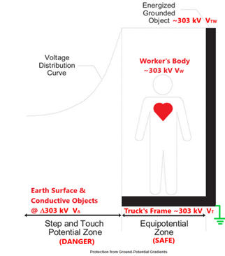
As depicted by Image #10, we can see when the truck’s grounded steel frame (VT) became unexpectedly energized at ~303 kV, the two linemen (VW) who were completely on and remained in direct contact with the truck’s steel frame also became energized at ~ 303 kV, VTW = VT – VW.
If VT = VW, then no current or insignificant current (I) flows between the two points.
As long as the linemen remain fully on the truck, a negligible amount of impedance/resistance exists between their bodies and the frame of the truck. Consequently, the minute voltage drop across the linemen’s bodies will result in an insignificant amount of current flowing through their bodies within the “let-go” threshold of 6mA. The truck’s body would be the safe equipotential zone (VT), but anything or anyone outside of it would be in the dangerous step and touch potential zone (V∆).
Time Duration
But just as important is the time (t) duration for the voltage potential of the truck’s body to rise from 0 volts to 303 kV (VTtr) to be identical as the time rate for the voltage potential of the linemen’s bodies to rise from 0 volts to 303 kV (VWtr). And when the protective relaying trips open and deenergize the line, the time required for the voltage potential of the truck’s body to drop from 303 kV to 0 volts (VTtd) must follow the same time decay rate as the voltage of the linemen’s bodies dropping from 303 kV to 0 volts (VWtd).
If VTtr =VWtr and VTtd = VWtr, then no current (I) flows between the two points during these near instantaneous moments in time.
VTW is the voltage difference between VT and VW
VTtr and VWtr is the voltage time rise between VT and VW
VTtd and VWtd is the voltage time decay between VT and VW
Image #10 – Safe Equipotential Zone vs. Dangerous Step and Touch Potential Zone
This same principle occurs during automobile accidents when the vehicle’s body becomes energized from downed powerlines. If the occupants remain inside the vehicle, they are within the equipotential zone, safe from electric shock hazards. But if any of the occupants attempt to exit the energized vehicle and contact both the vehicle and ground simultaneously, they enter the dangerous zone of step and touch potential hazards. And this topic takes us to our next discussion point regarding the foreman who was standing on the ground near the line truck.
The Danger Zone of Step and Touch Potential
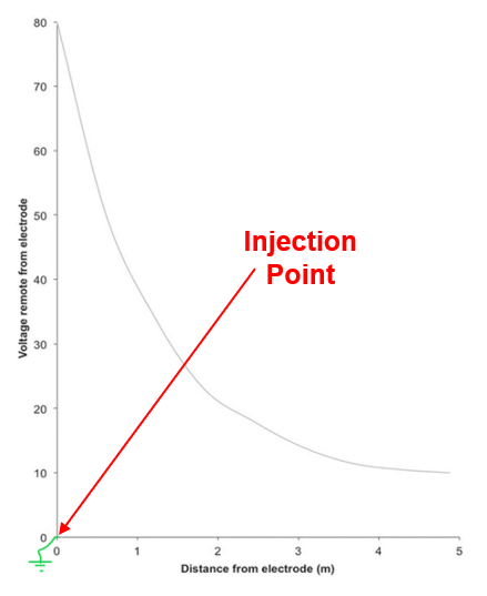
When high voltage current enters the earth and returns to its source, different voltage gradients develop in the surface of the soil in elongated irregular shapes resembling rough rings surrounding the injection point, AKA the grounding electrode. This is a phenomenon known as Ground Potential Rise (GPR). The highest voltage gradient is located at the point where the electric current initially enters the earth through the grounding electrode. As the subsequent voltage gradients move away from the injection point, the voltage potential of each gradient differs from the adjacent gradients due to the varying conductive values of the soil. According to OSHA 1910.269, Appendix E, Section II, this is known as the ‘Typical Voltage – Gradient Distribution Curve’ as shown by Image #11.
Image #11 – Example of Typical Voltage – Gradient Distribution Curve Assuming Uniform Soil Texture
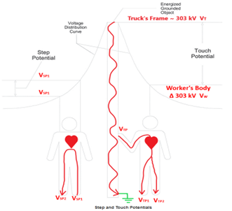
The figure on the right side of Image #12 is an example of the touch potential hazard the foreman was exposed to. As we can see, if the foreman (VW) is in contact with the truck’s body (VT) while standing on the earth simultaneously, then his body would be at a different voltage potential as the truck’s steel frame, which would place him in a parallel circuit for the fault current. For example, if the truck’s frame was energized at ~ 303 kV and the foreman’s hand is at 0 volts, then a potential difference of 303 kV would exist between the two points, where
VTW is the voltage difference between point VT and point VW,
VT is the truck’s frame, and
VW is the worker’s body.
In other words, there is a voltage difference between the truck’s frame with respect to the foreman’s body. Electric current would enter his hand at point VTP, flow through his arm to his chest area, divide between the two legs, and finally exit through his feet (VTP1) and (VTP2) back into the soil.
If VW ≠ VT, then current (I) will flow through VTP, divide between VTP1 and VTP2, and then return to its source to equalize itself.
The figure on the left side of Image #12 depicts a step potential hazard where the voltage between the two feet of a person standing near an energized grounded object has become energized. If the foreman was standing closer to the truck but not touching it, one foot VSP1 could be in a hypothetical gradient of 301 kV and his other foot VSP2 could be in a gradient of 298 kV. Then there would exist a difference of electric potential of 3 kV between his right foot and left foot, VSP1/SP2 = VSP1 – VSP2. Because of this difference in voltage between his two feet, electric current would enter the foot inside the highest gradient shown as VSP1, flow through one leg across his torso to the other leg, and then exit his other foot VSP2 located inside a lower gradient back into the soil.
If VSP1 ≠ VSP2, then current (I) will flow through VSP1 to VSP2 back to its source to equalize itself.
Image #12 – Examples of Touch and Step Potential Hazards
The Effectiveness of EPZ Grounding
While the evidence and analogy presented by using the flashover incident of the line truck during LLBHW to validate the effectiveness of EPZ grounding of deenergized lines and equipment isn’t supported by quantitative testing data, such as those derived from extensive and repetitive examinations in controlled laboratories, its qualitative values cannot be denied. The conclusion of the safety value of EPZ grounding when correctly installed is accurate and scientifically plausible in the opinion of the author.
The most compelling and supportive evidence for this conclusion is the undeniable fact that the two linemen on the bucket truck whose bodies were exposed to hundreds of thousands of volts were able to walk away completely unscathed. This is not a fluke occurrence or the product of happenstance. Rather, their survival substantiates with certainty that minimizing all differences of voltage potential in the work area is the key to effective temporary protective grounding.
This is because when VA is equal to VB, then IAB = 0 amperes (where IAB is the current flow between points VA and VB). In other words, the voltage of point VA with respect to point VB is identical, i.e. “equal.”
Therefore, if temporary protective grounds are “placed at such locations and arranged in such a manner that the employer can demonstrate will prevent each employee from being exposed to hazardous differences in electric potential,” then our workers will essentially become the proverbial ‘bird on a wire’ if the equipment they’re working on becomes unexpectedly energized.
This, of course, is undeniable electrical theory, but the challenge presented to all employers is the actual implementation of this simple theoretical principle by correctly applying it in the real world, taking into account the differences of environments, weather conditions, types of equipment and work locations our employees will be exposed to during their normal duties as qualified electrical workers.
For this reason, accurate engineering analysis performed by qualified electrical engineers who possess the technical skills, experience, and expertise with medium and high voltage power distribution systems is essential. The information from the analysis must be coupled with competent training provided by instructors who can transfer this valuable knowledge to the frontline electrical workers and their crew foremen in order to move the concept from the theoretical domain into the realm of the practical safety in the field, where the “EPZ rubber hits the road.”
Wrap Up
In Parts 1 through 4, we provided the regulatory requirements, some history of the various grounding practices, and a real-life event to show how these all tie together to offer facts and objective evidence that support the importance of equipotential zones when installing temporary protective grounding.
Next, as we head into the closing chapter of this multipart series in Part 5, we’ll share other pertinent lessons learned outside of EPZ based on the flashover event.
George Cole joined the e-Hazard team in 2021 as an electrical safety instructor and consultant specializing in the electric utility industry. He has worked for the largest electric utility company in Arizona for over three decades, holding various technical roles in several departments (building electrical maintenance, T & D, radio telecommunications, electric power generation, etc.). George is currently assigned to the Palo Verde Nuclear Generating Station as their electrical safety consultant and is the “Subject Matter Expert” (SME) in all matters related to electrical safety. George holds credentials as a Certified Electrical Safety Compliance Professional (CESCP) and a Certified Electrical Safety Worker (CESW) from the NFPA and serves as a member of NFPA’s Certification Advisory Group (CAG) for the CESCP and CESW. He is also a member of the Electrical Safety Industry Working Group (IWG) within the nuclear power industry, where he is considered an electrical safety expert among his peers.