In Part 1, we covered the regulations, standards and codes governing temporary protective grounding (TPG), especially the key element for them to be “placed at such locations and arranged in such a manner that the employer can demonstrate will prevent each employee from being exposed to hazardous differences in electric potential,” i.e., equipotential zone (EPZ) grounding.
Now, in Part 2, we’ll move into a little history lesson behind temporary protective grounding, and then review some former practices that are still used today but were later determined to be ineffective. We will also start to cover some of the basics surrounding EPZ grounding.
History of TPG
Temporary grounding of electrical equipment and power lines has been used by linemen and electricians since the advent of high voltage transmission and distribution systems across the nation. These old timers understood all too well that a “deenergized” line or equipment that was disconnected and isolated from its source could remain energized by outside factors, such as electromagnetic inductance or capacitive coupling from adjacent lines, transformer back feeds by portable generators, etc. So, they devised ingenious, albeit unverified, ways to keep the lines free from hazardous voltages and themselves safe while working on them.
They were also aware the line or equipment they were working on could be re-energized from its normal source through human errors, such as switching mistakes when the wrong isolation point is closed in by another crew or remotely by the operations control center. The latter situation is the primary factor for correctly sizing of TPGs to safely handle the maximum fault current. Originally, heavy steel chains or cables were selected to short the phases together, then either laid on the soil or connected to a ground rod as the “earthing” step. Copper wires and cables eventually replaced steel because of its better conductive properties. This led to the development of several related standards over the years, such as IEEE 1048, IEEE 1246, ASTM F855, ASTM F2249 and ASTM F2715, which we’ll discuss later.
Working Between Grounds?
How many have ever heard the saying, “Work between your grounds?” This was the original method selected when placing TPGs in relation to the work location and is known as “Bracket Grounding” or “Bracketed by Grounds.” This means two sets of grounding cables are placed on each side of the workers, often hundreds or thousands of feet from the actual work location, oftentimes well out of sight. This led to the popular but deadly saying “work between your grounds.” This methodology became the norm for many decades.
The thought process behind bracket grounding was a flawed belief. If the line or equipment became reenergized, fault current would be completely shunted around the workers through the two sets of grounds installed on each side of them.
As data from incidents in the field and laboratory testing started trickling in, bracket grounding was found to be ineffective and placed the workers in great danger of electrocution. This is because bracket grounding positions the worker(s) in a parallel circuit while they’re in contact with the line or equipment.
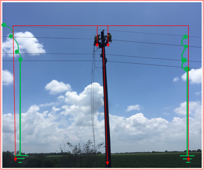
As we know, a parallel circuit divides current through each of the parallel branches proportionally based on the resistance of each branch, as shown by Image #1. For full disclosure, the lineman on the left side of the photo is my favorite nephew, Tommy Cole. Sadly, he betrayed the family by becoming a lineman rather than an electrician, so his status in the Cole clan is questionable at this time.
Image #1, Bracketed Grounding Configuration
While true the low resistances of the copper ground cables on each side of the workers will carry the majority of the current, it does not carry all the current. This means some current will still flow through the workers. We mustn’t forget it only takes about 20 to 100 mA for ventricular fibrillation to occur.
Let’s do the math…and physics
Let’s say the available current on this stretch of line is 35,000 amps and the ground cables are able to shunt 34,999 amps due to their size and rating, which would be more than 99.99% of the fault current. This leaves “only 1 amp” that’s not picked up by the grounding cables.
So where does that one single ampere go (because the earth doesn’t absorb it and make it magically disappear)? That’s correct – it will flow through the two linemen who are in parallel with the two ground sets on both sides of them at about 0.5 amps each. And one half of an ampere (0.5 amp) is significantly greater than the 20mA (0.02 amp) ventricular fibrillation threshold. For this reason, OSHA deems hazardous current exists if the level is more than 6 mA according to Appendix C from 1910.269 Subpart R and 1926 Subpart V.
Appendix C refers to an equation derived from IEEE 1048 – 2003 IEEE Guide for Protective Grounding of Power Lines to help employers determine the threshold of ventricular fibrillation when the duration of the electric shock is limited.
I = the current through the worker’s body
t = the duration of the current in seconds.
The equation represents the ventricular fibrillation threshold for 95.5 % of the adult population with a mass of 50 kilograms (110 pounds) or more. The equation is valid for the duration of current exposures between 0.0083 to 3.0 seconds (< 1 cycle to 180 cycles in a 60 Hz system).
But let’s not forget current levels as low as 16mA can prevent the release of your grip from around an object (‘let go’ threshold), and 20mA can cause paralysis of respiratory muscles, meaning breathing is very difficult. * If you can’t let go of the conductor, then the duration of the shock isn’t limited, and the longer you find yourself in series of the circuit, the longer deadly current will flow through your body, which lessens your chances of surviving a “minor” electric shock.
Sadly, the ineffective and dangerous practice of bracket grounding is far too common even today and is still utilized throughout the country by some electric line workers. You’ll hear many a lineman or utility electrician insist they have to “Work between Grounds” as the only way to remain safe by the TPG.
But the worker can’t be blamed for this erroneous belief because it’s the employers’ responsibility to provide technically accurate electrical safety training to their employees. Electric utility workers have been taught this relatively simple, albeit hazardous, concept of “working between grounds” for decades, passed down from journeyman to apprentice and from generation to generation without anyone questioning its efficacy or reviewing the current safety regulations governing it.
Since 1994, OSHA has limited installations of TPGs to only one approved method and practice known as equipotential zone (EPZ) grounding, sometimes called “single point grounding.” EPZ grounding is founded on the singular key sentence:
“Temporary protective grounds shall be placed at such locations and arranged in such a manner that the employer can demonstrate will prevent each employee from being exposed to hazardous differences in electric potential.”
Hence, bracket grounding by itself is no longer recognized as the sole approved practice or viable option according to federal labor laws because it has been proven to be ineffective. However, bracketed grounding can be used in conjunction with single point grounding to develop an effective EPZ.
The basic premise of EPZ grounding is founded on the principle of establishing a “work area” that ensures any difference of electrical potential between the worker, the deenergized line or equipment being worked on (i.e., being touched) and all other conductive equipment in close proximity to the worker is maintained “as low as possible.” So, if the parts being touched become reenergized, the voltage drop across any two points (the worker and what he or she is in contact with) in the work area is limited to the lowest value possible. This is primarily accomplished by ensuring very low resistance and impedance bonding exists between all conductive parts in the work area; the deenergized parts being touched; the neutral conductor, if present; and the worker.
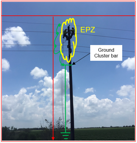
By taking the TPGs installed in Image #1 and moving them as close as practical to the work location, shorting all the phases together, connecting to the neutral or “static” wire and pole ground (if installed), and then placing a “ground cluster bar” below their feet, which is in turn bonded to a grounding point, the linemen on the pole will be enclosed within a virtual “EPZ bubble,” as shown by Image #2. Since everything inside the EPZ bubble will be at the same or very near the same electrical potential, then any current flowing between the various points is minimal.
EPZ is officially called “single point” grounding due to only one set of TPGs in use. However, many companies employ a combination of both EPZ grounding with bracketed grounding, which isn’t required but most certainly is a best practice.
But bracketed grounding without creating an EPZ at the work location can be a deadly mistake.
Image #2, EPZ Grounding Configuration
EPZ at the Ground Work Area
So, what about those electricians who prefer not to work on power poles? Can EPZ be employed to protect them from dangerous electric shock? The answer is an unequivocal YES.
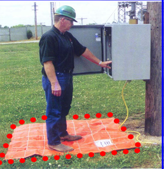
Several manufacturers provide portable EPZ bonding mats that can be easily used with medium voltage distribution equipment commonly found in industrial locations and power generation plants, such as metal clad switchgear, pad mounted transformers, bus ducts, motors, switching cabinets, etc. These portable, highly conductive pliable mats are manufactured per ASTM F-2715 Standard Specification for Temporary Protective Equipotential Bond Mat To Be Used on De-Energized Equipment and can help such workers quickly and effectively develop a zone of equipotential at the point where they’re working, as shown in Images #3a & 3b. But for them to be effective, all parts of the worker’s body must remain within the perimeter of the EPZ bonding mat.
Image 3a
Image 3b
Images 3 a & b: Portable EPZ Conductive Mats, Both feet and all body parts must remain within the perimeter of the EPZ mat
Now that we’ve covered the basics of EPZ grounding, in Part 3 we’ll start to delve into the “meat” of EPZ grounding, i.e., preventing shock hazard from hazardous differences in electrical potential and why it’s so effective when correctly installed. To do so, I’ll use a real-life example that some may find quite odd and possibly even contradictory for the whole purpose of temporary protective grounding in the first place.
George Cole joined the e-Hazard team in 2021 as an electrical safety instructor and consultant specializing in the electric utility industry. He has worked for the largest electric utility company in Arizona for over three decades, holding various technical roles in several departments (building electrical maintenance, T & D, radio telecommunications, electric power generation, etc.). George is currently assigned to the Palo Verde Nuclear Generating Station as their electrical safety consultant and is the “Subject Matter Expert” (SME) in all matters related to electrical safety. George holds credentials as a Certified Electrical Safety Compliance Professional (CESCP) and a Certified Electrical Safety Worker (CESW) from the NFPA and serves as a member of NFPA’s Certification Advisory Group (CAG) for the CESCP and CESW. He is also a member of the Electrical Safety Industry Working Group (IWG) within the nuclear power industry, where he is considered an electrical safety expert among his peers.