In Part 2, we covered the good and some of the not-so-good history about temporary protective grounding (TPG) with a few of the basics surrounding EPZ grounding.
Now as we progress into Part 3, we’ll move into the matter a little deeper to show why the elementary principles of equipotential zone grounding are effective. To do so, I’ll use an incident with real life and death consequences to demonstrate the similarities between EPZ grounding and a very specialized work practice called “Live Line Bare Hand Work” (LLBHW).
What is Live-Line Bare Hand Energized Work (LLBHW)?
For those not familiar with the term Live Line Bare Hand Work (LLBHW), it’s also known as “bare hand method” or “bare handling.” It is a very controlled and dangerous work practice where highly trained workers use specialized techniques and equipment to intentionally make physical contact with one phase of a high voltage AC overhead line while energized at full nominal phase to ground potential, at the magnitude of hundreds of thousands of volts. Yes, you read correctly, I said these people intentionally touch power lines with their hands while it’s still energized at hundreds of thousands of volts.
This is where some readers may be scratching their heads right about now and asking the question, “How is working on a de-energized line that’s temporarily grounded related in any way with working on the same lines while they’re still energized?” That’s a fair question. As we progress through the presented evidence, I’m confident you’ll see the connections.
LLBHW is limited to overhead open air transmission lines and equipment through the “bird on the wire” concept and is normally employed with transmission voltages of > 100kV, based on ANSI C84.1-2006 – American National Standard for Electric Power Systems and Equipment Voltage Ratings (60 Hertz).
From a federal safety regulatory position, LLBHW is permitted and governed by 29CFR 1910.269(q)(3) for operations and maintenance and 1926.964(c) during construction. So, if it is permitted by OSHA, then we can conclude there’s a safe way to perform this very dangerous activity.
For obvious reasons, NFPA 70E® does not have any provisions for LLBHW anywhere in the standard.
As you can guess, many critical prerequisites must be carefully followed and in place before the employer permits his employees to perform LLBHW. The five most important requirements for LLBHW as it relates to EPZ grounding are as follows:
Maintain physical distances from other energized parts at different voltage potential and from grounded parts. In other words, keeping outside of the Minimum Approach Distance (MAD), which is very similar to 70E’s Restricted Approach Boundary (RAB) for shock protection.
The employee shall use an aerial bucket with a conductive liner.
The employee’s body is bonded to the bucket liner and all the other conductive parts around him.
Uninsulated equipment or materials shall not be passed to or from the employee while he is bonded to the energized line.
If a difference of potential exists, then the employee shall use “electrostatic shielding,” which is a type of specialized conductive clothing.
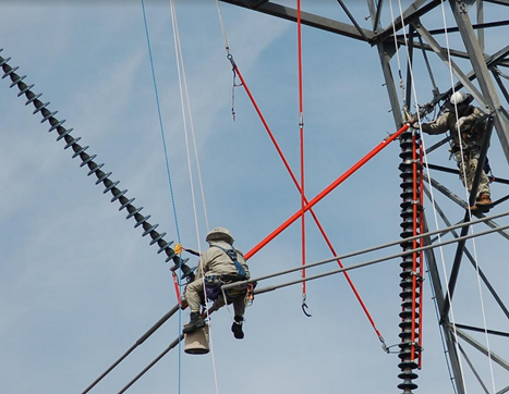
As we can see from these five crucial contingencies, especially the last “if/then” conditional statement that triggers the need for “electrostatic shielding” as a compensatory action if potential differences exist, the key is eliminating any differences in potential. Electrostatic shielding in the case of LLBHW is a special, highly conductive suit, which is essentially a wearable Faraday cage. When energized, it acts as an electrical shield where the charges appear only on the surface of the conductive clothing with no effect on the interior portions of the suit which houses the worker’s body, as shown by Image #4.
Image #4 – Linemen wearing Conductive Electrostatic suits while seated on an energized 525 kV power line
These fundamental principles that sustain safe LLBHW are nearly identical to those required for EPZ grounding. By maintaining an area of equal potential between the worker(s), the energized line/equipment and all other conductive objects in close proximity to him, the worker is physically placed within an equipotential zone (EPZ). But with LLBHW, unlike EPZ grounding, the worker must maintain his MAD from not only other energized parts at different potentials, but he must also keep his distances from all grounded parts.
This is because anything or anyone who is at or has the ability to contribute to a different voltage potential during LLBHW can cause an incident with deadly consequences.
With these elements in mind, I’ll share the real-life incident at my power plant briefly discussed in Part 1 where LLBHW activity went terribly wrong. But this incident provides objective evidence that EPZ grounding, if installed correctly, is effective in keeping workers safe.
The Event at My Power Plant
As with most power generating stations, my nuclear generating plant uses a switchyard constructed in a two-bus configuration as the demarcation point between the plant and our interconnection to the 525kV transmission grid. The layout of the switchyard consists of one bus located at the east end of the yard called the “East Bus” for obvious reasons and the opposite bus is titled the “West Bus.” The East Bus is primarily used to feed several 525kV “extra high voltage” (EHV) lines, leaving the switchyard to feed the nation’s southwest transmission grid network, while the West Bus is used to connect the plant generators’ step-up (GSU) transformers to the switchyard and, ultimately, the grid.
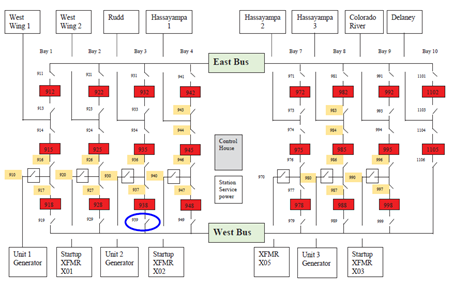
ANSI C84.1-2020, Electric Power Systems and Equipment – Voltage Ratings (60 Hertz) defines EHV as having a nominal voltage potential from 345 to 765kV. In a typical switchyard configuration, several bays containing breakers and their associated motor operated disconnect (MOD) switches are placed between the two buses for sectionalizing and isolation, as shown by Image#5.
Image #5 – 525kV Switchyard Layout
While my power company has exclusive operational control over the entire generation portions of the station, the switchyard, on the other hand, is under joint control with another separate and independent electric utility company, who will be referred to and identified as “Company A” for the remainder of this article. Legal agreements and procedures are in place to ensure any activities inside the switchyard are coordinated with the control rooms of the generation plant.
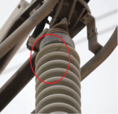
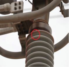
During routine inspections inside the switchyard by Company A, stress cracks, as shown in Image #6, were observed in two different porcelain insulators associated with MOD 939, which is connected to the West Bus and is enclosed by the blue circle in Image #5. These cracks in the insulators’ bodies were severe enough that they could compromise the integrity of the electric equipment mounted to them.
Unlike standard insulators found on transmission towers, these insulators provide not only the insulative barrier between the energized parts mounted on top of them from the grounded steel frame below them, but they also provide physical rigidity and corrective alignment of all the interconnected moveable mechanical parts. When the MOD is opened or closed, through large motors and gear drives, tremendous amounts of mechanical torque stress is imposed on these insulators.
Image #6, Stress Cracks in Insulators
Due to the risk of catastrophic failure of the insulator, it was imperative they be promptly replaced. After much deliberation and planning by all stake holders, a decision was made to facilitate repairs without de-energizing and grounding the West Bus to minimize impacts to the station’s nuclear operations. Because Company A is responsible for all maintenance within the switchyard, a specialized crew of very experienced LLBHW linemen, also known as “hot work” linemen, from Company A were selected to change out the cracked insulators.
The repair work was scheduled and then executed during early October 2018. Weather conditions were normal for that time of the year, warm and humid, in Arizona’s desert climate. The sky was slightly overcast with large cumulus clouds, and the average ambient temperature was in the range of the 80°- 90°F. Rainfall the previous day accounted for an elevated humidity level with subsurface soil conditions very moist and damp but not muddy.
The line crew from Company A used a very specialized insulated bucket truck designed for LLBHW with a dielectric rating suitable for “extra high voltage” (EHV) transmission lines and equipment. Once the truck was parked in place, the four outriggers were set and the vehicle’s steel body and frame bonded to the switchyard’s 4/0 copper underground grounding grid through the truck’s 2/0 AWG copper cable and clamp assembly.
The truck’s grounding cable is stored on a specially designed steel storage reel mounted at the nose of the vehicle directly in front of the radiator and above the front bumper. The grounding cable is connected to a termination point within the storage reel through a grade 2 crimped copper ferrule which effectively bonds the grounding assembly to the truck’s steel frame. Non-conductive yellow and black ribbon barrier tape, used with fluorescent orange traffic safety cones, established an area around the truck’s perimeter to prevent unauthorized persons from entering the energized work area.
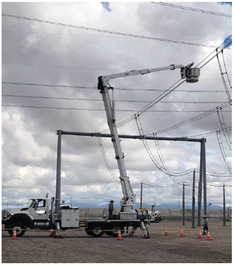
The boom was then elevated via the lower controls located at the base of the hydraulic turret by one of the two linemen who were both standing on the steel bed of the truck. The boom was slowly uncradled and then lifted until the stainless-steel-lined fiberglass bucket made contact with one phase of the West Bus, in this case ‘A’ phase, as shown in Image #7.
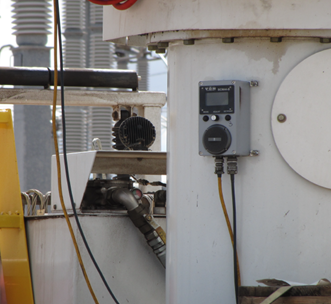
Once the bucket was energized at full phase to ground potential, approximately 303 kV, it remained in contact with the conductor as the linemen on the truck monitored the amount of leakage current through the fiberglass portions of the boom. This was accomplished by an analog ammeter that read the minute amount of current leaking from the energized bucket through the insulated fiberglass boom segments to the truck’s steel body frame, to the grounding cable reel and finally to the switchyard’s ground grid, as shown in Image #8.
OSHA regulations specify the test of the boom’s dielectric property shall be performed for a minimum of three minutes with a maximum permissive current leakage of 1µA per kV for the nominal phase to ground voltage, which would have been in the range of 300 µA in this case. To provide a conservative safety margin for their employees, Company A administratively sets the maximum acceptance criteria for current leakage at 289 µA for 500/525kV lines and equipment, which is lower than OSHA. However, according to the foreman from Company A, the typical leakage current experienced during testing of similar transmission voltages is substantially lower, somewhere in the range of 120 µA.
Image #7 – Actual Pre-use Insulation Test by Company A Prior to Event, One Lineman visible while the other is positioned behind the boom turret and is obscured from view
Image #8 – Current Leakage Ammeter Mounted on the pedestal of the boom
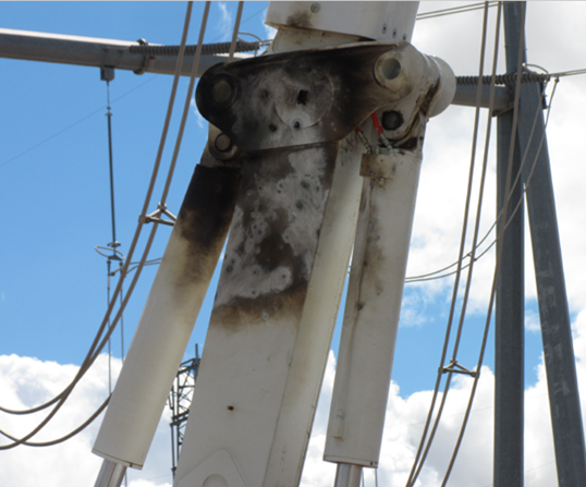
During the dielectric insulation test, everything initially appeared to be normative with leakage current well within the expected criteria of approximately 120 µA. However, without warning, leakage current unexpectedly increased rapidly and before the linemen could disconnect the bucket from the energized line, a flashover, AKA “arc over” occurred, causing a substantial ground fault event. The subsequent ground fault actuated the protective relaying which tripped all eight (8) breakers clearing the West Bus within a few cycles; the estimated time was approximately 4 to 6 cycles (0.0667 seconds to 0.010 seconds). But in that nearly instantaneous time frame, significant damage had already occurred to the bucket line truck, as shown by Image #9.
Image #9, Damage to Bucket Line Truck from flashover
What caused the catastrophic failure and, more importantly, what were the consequences for the workers involved? I already spilled the beans in Part 1 by revealing the workers walked away uninjured, so in Part 4 we’ll cover some of the reasons that led to their ability to survive such a life-threatening event by connecting the dots between LLBHW and EPZ grounding using the learnings gleaned from this event.
At the time of this article, the investigation is still in progress, trying to ferret out the root and contributing causes.
George Cole joined the e-Hazard team in 2021 as an electrical safety instructor and consultant specializing in the electric utility industry. He has worked for the largest electric utility company in Arizona for over three decades, holding various technical roles in several departments (building electrical maintenance, T & D, radio telecommunications, electric power generation, etc.). George is currently assigned to the Palo Verde Nuclear Generating Station as their electrical safety consultant and is the “Subject Matter Expert” (SME) in all matters related to electrical safety. George holds credentials as a Certified Electrical Safety Compliance Professional (CESCP) and a Certified Electrical Safety Worker (CESW) from the NFPA and serves as a member of NFPA’s Certification Advisory Group (CAG) for the CESCP and CESW. He is also a member of the Electrical Safety Industry Working Group (IWG) within the nuclear power industry, where he is considered an electrical safety expert among his peers.