What Does a Digital Multimeter Do?
Digital multimeters (DMMs) are very complex electronic devices that can measure many different values with extreme precision. As the name “multi-meter” implies, these test instruments have more than one function, compared to a single purpose voltmeter or ammeter, but a DMM’s primary function is to accurately read voltage and current.
The Challenge for Some DMMs
All good quality DMMs will provide very accurate testing of AC voltage and current when sampling sinusoidal or “sinewaves,” especially when reading what is called “pure sinewaves.” But sometimes the sinewave is not so “pure.” This reality in today’s circuits can pose challenges with some DMMs.
Recall from Part 1 that AC is a sinewave, meaning the voltage and current changes polarity from positive to negative 60 times a second. The reason for this very smooth oscillating sinusoidal waveform is because, in the past, most AC sources were produced from generators with most connected loads being linear.
The Generator
A generator is a device that converts chemical and/or mechanical (kinetic) energy into electrical energy through electromagnetic induction, which was first discovered by Michael Faraday, a British scientist from the middle 1800s.
But it was Nicola Tesla, an American of Croatian descent, who innovated the use of AC rather than DC for electrical distribution systems and later for transmission of electrical energy over long distances. In fact, Tesla is often known as the “Father of today’s AC generation, distribution and transmission systems.”
A typical generator consists of a fixed oval part resembling a ring called a “stator.” It has a second moveable part called a “rotor” spinning within it, as shown in Figure 5.
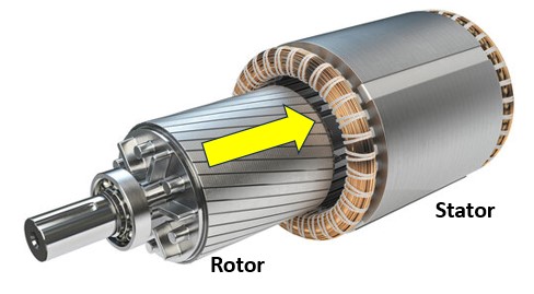
The stator has coils of insulated wires or bars wrapped around an iron core that produces a magnetic flux field, either through an electro-magnet or fixed magnetic. The rotor, too, will contain winding coils with a laminated steel core.
A “prime mover” provides the mechanical energy needed to turn the rotor; for example, a steam or water turbine, internal combustion engine, wind blades, etc.
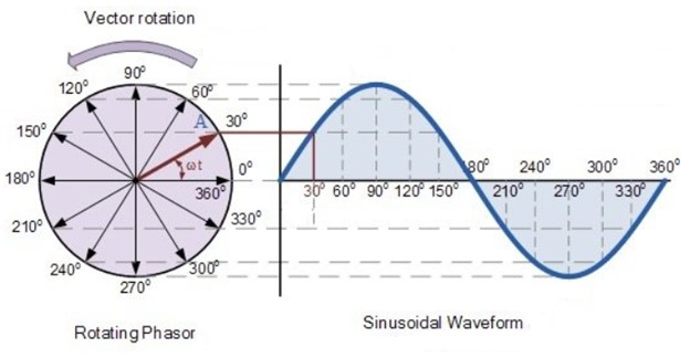
When the rotor is turned in a circular movement, it cuts through magnetic flux with varying densities offered from the stator, which is divided into 360 degrees as a circle. This movement induces a varying voltage and current in the form of a sinewave.
The greater the density of magnetic flux, the greater the subsequent induced voltage and current. Figure 6 shows the relationship of a rotating phasor with its corresponding sinewave.
New Waves
In the early days of electrical energy, nearly all AC circuits were pure sinewaves, but with the introduction of electronic technologies, such as semi-conductors, variable frequency drives, solid state lighting controls, data centers, digital power supplies, inverters, etc., the smooth oscillating AC sinewave was affected, and in some cases, significantly.
New types of waves were developed; for example, saw-tooth, square-waves, pulse-waves, triangular-waves, modified sinewaves, and a vast number or other irregular waveforms from sources other than generators combined with harmonic distortion and/or connections to non-linear loads.
These atypical waveforms can negatively affect the accuracy of certain types of DMMs, especially when taking AC voltage and current readings.
Some Differences Between Averaging and RMS DMMs
Averaging RMS/Average Responding meters were engineered and designed with mathematical algorithms to specifically measure pure sinusoidal waves, such as those produced by generators.
However, when an Averaging RMS/Average Responding meter is used with non-sinusoidal waveforms or those with significant harmonics, its accuracy can be substantially compromised. According to the Fluke® Corporation, this inaccuracy can range from a value of up to 40% low to a 10% high reading, as shown by Figure 7.
Such inaccuracies can add unnecessary frustrations and uncertainty during troubleshooting and testing, which may increase the risk of a mistake or accident, and, thus, the wrong solution to the problem because the causes were not correctly identified.
However, a True RMS meter has the capability of providing accurate readings regardless of the waveform being sampled.
Trust But Verify!
As interesting as these numbers may be, we as electricians and technicians sometimes need visual proof to validate such claims. Many of us come from the old school of ‘Seeing is Believing’ or ‘Trust but Verify.’ This is a much-needed trait in today’s world.
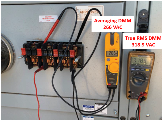
That said, Figure 8 shows two Fluke DMMs connected in parallel to the same two points of test switches. The DMM on the left is an Averaging-RMS type while the other on the right is a True-RMS DMM.
The Averaging-RMS DMM is reading 266 VAC while the True-RMS is displaying the correct and expected system voltage of approximately 319 VAC. As you can see, there is a significant 53-volt difference between the two, which equates to slightly over 18% low for the Averaging-RMS meter.
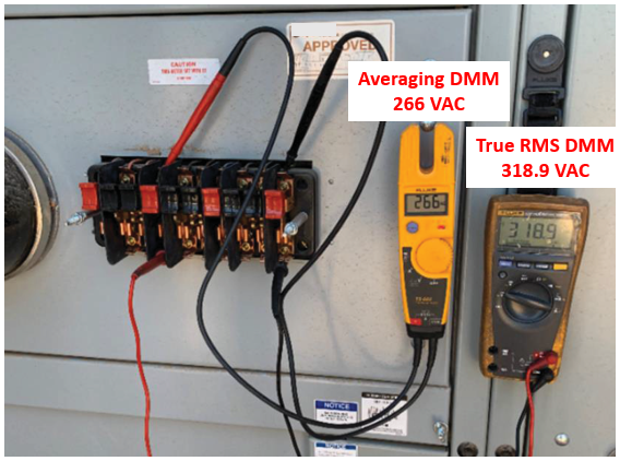
In this incident, several contributing factors were responsible for the deltas in the voltage readings; however, the bottom line is the True-RMS meter was spot on regardless of the voltage being sampled, be it a pure sinewave or not.
Determining Which Meter to Use
So, how do you determine if your DMM is a True-RMS or Averaging Responding RMS meter? Most high quality DMMs will proudly display the words “TRUE RMS” somewhere on the meter, and, in my experience, it is normally found on the meter’s face, as shown by Figure 9 of three different True-RMS meters.
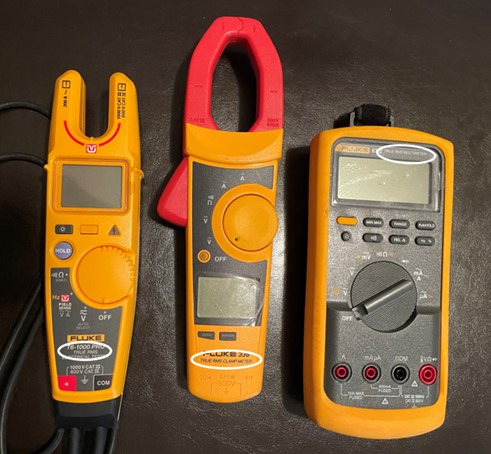
But, like everything else, this may not always be the case. If your meter does not indicate one way or the other, then your only option is to dust off the paper copy of the instructional safety manual (if you can find it) to ascertain this important information.
If you are unable to locate your hardcopy, you can probably obtain a pdf copy for your specific model online because most reputable makers of high quality DMMs make them available on their website free of cost.
However, even if your DMM shows it is a True-RMS type on the meter itself, it is always a good practice to review the user’s safety manual from time to time. You might be surprised at the additional information you can learn from its contents, especially as it relates to safety.
Conclusion
In conclusion, if your work is limited to taking simple voltage and current checks of residential type electrical or electronic equipment, then an Averaging-RMS DMM may be adequate for your needs. The cost difference between the two meters is minimal, so we at e-Hazard strongly encourage the use of True-RMS meters even for residential applications.
On the other hand, if you are an electrician or test technician tasked with troubleshooting and maintenance activities inside large industrial plants, data centers, manufacturing facilities, electric utilities and power generating plants, or other similar locations with complex electric distribution systems, then a True-RMS meter is an absolute must.
Those who work on electric vehicles (EVs) should also choose True-RMS meters as well. Many mistakenly think EVs are limited to only DC and assume they will not use or need the AC function. What they do not realize is many EVs contain inverters which convert DC into some form of single-phase and poly-phase AC for countless secondary functions, where the inverted AC will not be pure sinewaves but rather some type of atypical waveform.
Therefore, spending a little more money to buy a True-RMS meter will provide you with a significant return on your investment, not only with better troubleshooting accuracy and less frustration, but, more importantly, will also add greater controls for your personal safety.
* Image in Figure 7 is from a Fluke article, What is True RMS?

