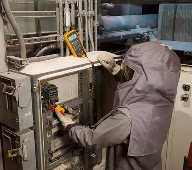
In the previous three parts, Part 1, Part 2 and Part 3 of this article series, we discussed some general attributes of digital multimeters, common mistakes in using them, their limitations, the training requirements, PPE to wear, and proven good practices when using digital multimeters (DMMs) as they relate to personal safety.
Now we will move to a topic that confuses so many people: the enigma of the CAT rating.
What is the CAT Rating?
We formerly discussed that NFPA® 70E®, 110.6 requires test instruments, test equipment, and their accessories to be “Rated for circuits and equipment where they are utilized.” This drives us to another safety concern, albeit a relatively unknown topic related to DMMs – their CAT rating, which can be confusing for many people.
If you have ever looked closely at your DMM, you probably read the word “CAT” followed by a Roman numeral value of I, II, III or IV accompanied by a voltage. This same information is also found on your test leads and probes.
Fig. 13 shows the CAT rating on a typical high quality DMM, and Fig. 14 shows the test probes. The rating of the probes is determined by the amount of exposed metal showing from the tips, so the CAT rating of test probes can vary depending on how much metal is covered.
Figure 13 - DMM Category III 1kV / IV 600V Rating
For example, the probes shown in Fig. 14 are equipped with permanent but retractable sheaths/sleeves that slide up and down the metal shaft when the probe is rotated. Those can be locked into one of two positions. The right image shows the protective sleeve fully extended with ‘CAT III 1kV / CAT IV 600V’ visible in the shutter window. The left image has the sheath completely retracted, exposing the entire length of the metal tip with the shutter window and now displays a lower ‘CAT II 1kV’ rating.
Fig. 14 - Test Probe Category Ratings
Some models and brands of probes have permanent covers with a fixed CAT rating while others are designed with snap on type removable tip covers.
What does all this mean, and how does it relate to your safety?
While most power circuits provide a steady state system voltage with little fluctuation outside of their maximum and minimum permitted ranges as established by Table 1 of NEMA/ANSI C84.1, Electric Power Systems and Equipment – Voltage Ratings (60 Hertz), momentary transient voltage spikes can occur. Such unexpected instantaneous events can lead to significant rise from the normal voltage.
Such phenomena are caused by lightning storms, faults, short circuits, perturbation on the electric grid, or switching activities of large high-power motors and inductive loads and various other external and internal factors.
Locations with the greatest probability of unexpected increases of voltage amplitude will be in the area of the main service point or service entrance section (SES) where the customer’s facility electrical system derives its power from the electric utilities. They can also occur within a facility at or near faults or when large electrical equipment is switched on or off.
These short-term voltage transients can cause internal arcing and a flash over within the test instrument which could result in its failure and personal injury to the user. One of the reasons UL/IEC 61010-1 Electrical Equipment for Measurement, Control, and Laboratory Use, Part 1 was updated was to minimize the negative impacts from voltage transients when using portable test equipment and their accessories.
Fig. 15 shows examples of overvoltage transient impulse spikes of a typical 60 Hz sinusoidal waveform.
Fig. 15 - Overvoltage Transient Spikes
As the momentary overvoltage transient travels through the electric equipment inside the facility or building, its magnitude is attenuated by the accumulated impedances within the distribution system which is further aided by lower available fault current from smaller downstream overcurrent devices (OCPD).
Overvoltage transients can also be minimized by the strategic use of permanently installed surge protective devices (SPD) with low voltage (< 1kV) equipment and surge arrestors in systems over 1kV, according to Article 242 of the National Electrical Code® (NEC®).
Fig. 16 is presented to assist the reader to better understand the relationship between the reduced voltage spike within the corresponding four category (CAT) zones following a lightning event. This image shows the various CAT zones consisting of I – IV of a typical large industrial plant following an overvoltage transient event, starting with the CAT IV zone with the highest transient threat on the right at the utility service entrance and moving to CAT I on the far left with the transient reduced well within the facility.
Fig. 16 - Typical UL/IEC 61010-1 CAT Zone Locations
Fig. 17 provides a helpful chart of the four UL/IEC 61010-1 overvoltage categories with a brief description of each, followed by some examples.
Fig. 17 - UL/IEC 61010-1 CAT I-IV Examples
Individuals working for or within electric utilities, power generating stations, renewable energy and storage facilities, large industrial plants, substations, data centers, main service entrance sections, and other similar locations with increased risk of a transient overvoltage condition should always use high quality DMMs and leads clearly marked CAT III/CAT IV. This is because these locations are most prone to such impulse transients.
Purchase Genuine High Quality DMMs From Reputable Sellers
As previously mentioned, the correct use and rating of test instruments is important to your personal safety, so it is just as important to ensure you’re using genuine, certified equipment.
Because of the plethora of counterfeit and unsafe DMMs from unscrupulous dealers flooding the US market, many with counterfeit certification labels, they should be procured from only reputable distributors rather than unknown online sellers offering you a “screaming deal” for a digital multimeter.
The adage, “If it’s too good to be true, then it’s probably not,” should be considered when buying DMMs and their accessories.
RMS vs Averaging DMMs
While not directly related to personal safety when using DMMs, the specific type of DMM selected can also indirectly impact your safety by providing inaccurate data.
This area of concern stems from the use of a True RMS (root means square) versus an Averaging Responding Voltage DMM. In today’s modern world of atypical waveforms, from high frequency switching power supplies, programable logic controllers, variable frequency drives, harmonic distortion and non-linear loads, only a true RMS DMM will provide the accuracy needed when troubleshooting these specialized circuits.
Warning – Not All ‘Category Ratings’ Mean the Same Thing
Finally, there are different categories of ratings which do not mean the same thing. To eliminate any confusion, we must clarify that the CAT rating of I, II, III, or IV we are discussing in this article and the rating stamped on the DMM or leads ARE NOT RELATED to the arc flash category rating of personal protective equipment (PPE).
PPE category arc ratings are identified by the numbers 1, 2, 3 or 4 as listed in NFPA70E, Tables 130.7(C)(15)(a), (b) or (c) or found on the labels of your arc rated (AR) garments.
The category (CAT) rating on your DMM and test leads is derived from a different standard, UL/IEC 61010-1, which has nothing to do with arc flash protective PPE that’s worn but rather the meter that’s being used and its ability to safely handle momentary overvoltage transients or spikes without failing.
One easy way to distinguish the difference is to remember the NFPA 70E PPE categories use the Arabic numeric values of “1,2,3,4” while UL/IEC 61010-1 uses the Roman numerals “I, II, III, IV.”
Conclusion
Within the four parts of this article series, we have underscored the critical importance of understanding and correctly using these marvelous tools called DMMs within their intended use, limitations, and listed and labeled instructions. We also shared several other requirements, including the need for adequate training according to workplace safety regulations and standards that must be complied with.
In summary, I have included the following lists of helpful “Do’s” and “Don’ts” for safe DMM use:
Do's
Always double-check the leads are plugged into the correct ports and the DMM is correctly set for the function you’re about to perform. Consider using jack plug covers to seal the current ports.
Always provide and document training for all models of DMMs and test instruments employees must use.
Always wear adequate level and rating of shock and arc flash PPE when using DMMs.
Always perform a visual inspection of your DMM and test leads for any damage prior to use.
Always use the correct CAT rating (I, II, III, IV) DMM and test leads suitable for the specific work location zone.
Always purchase high-quality DMMs and test leads from reputable retailers.
Always ensure your DMM has a certification from a Nationally Recognized Testing Laboratory (NRTL).
Always read and adhere to the safety warnings found in the DMMs user’s manual.
Consider using a basic but high-quality DMM equipped with only the functions you need.
Don'ts
Never exceed the voltage rating of your DMM or test leads.
Never fabricate your own test leads for use on circuits greater than 50 volts ac or dc.
Never modify or attempt to repair damaged test leads or malfunctioning DMMs.
Never purchase questionable or inferior DMMs from budget retailers or unknown online sellers.
Never assume that a job title such as “Journeyman,” “Test Technician,” “Electrical Engineer,” or years of experience automatically qualifies a person to use all styles of DMMs.
Failure to adhere to any of the prohibited actions and safety rules can cause (and have already caused) serious injuries and fatalities for the users that should be completely avoidable. Consistently employing the proven safety practices will decrease your risk of injury and increase your chances of going home to your families rather than your family visiting you in an emergency room.
NFPA 70®, National Electrical Code®, NEC® , 70E®, and Standard for Electrical Safety in the Workplace® are registered trademarks of the National Fire Protection Association, Quincy, MA.
George Cole joined the e-Hazard team in 2021 as an electrical safety instructor and consultant specializing in the electric utility industry. He has worked for the largest electric utility company in Arizona for over three decades, holding various technical roles in several departments (building electrical maintenance, T & D, radio telecommunications, electric power generation, etc.). George is currently assigned to the Palo Verde Nuclear Generating Station as their electrical safety consultant and is the “Subject Matter Expert” (SME) in all matters related to electrical safety. George holds credentials as a Certified Electrical Safety Compliance Professional (CESCP) and a Certified Electrical Safety Worker (CESW) from the NFPA and serves as a member of NFPA’s Certification Advisory Group (CAG) for the CESCP and CESW. He is also a member of the Electrical Safety Industry Working Group (IWG) within the nuclear power industry, where he is considered an electrical safety expert among his peers.